Analog Audio Output Levels & Input Matching
Across Consumer Electronics, Professional Audio, and Cinema Systems
In analog audio design, there is no single universal “correct” output voltage. What matters is not an absolute number, but how well the source output level, input sensitivity, input impedance, and overall gain structure work together in a given application.
This article outlines how analog output levels differ across consumer, professional, and cinema environments—and how to properly design the receiving side, including impedance considerations.
- Consumer Electronics
(RCA / 3.5mm / Unbalanced Systems)

Typical devices:
- Smartphones, tablets, laptops
- TVs
- Blu-ray players
- Music streamers
- Home DACs / amplifiers
Typical output levels:
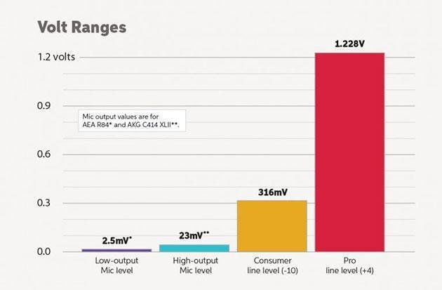
0.316V RMS to ~2V RMS
Common references:
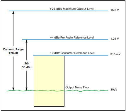
- 0.316V RMS (~ -10 dBV) → traditional consumer line level
- 1V RMS → widely used in modern devices
- 2V RMS → typical for CD players and DAC full-scale output
Design priorities:
- Simplicity
- Low cost
- Short cable runs
- Ease of integration
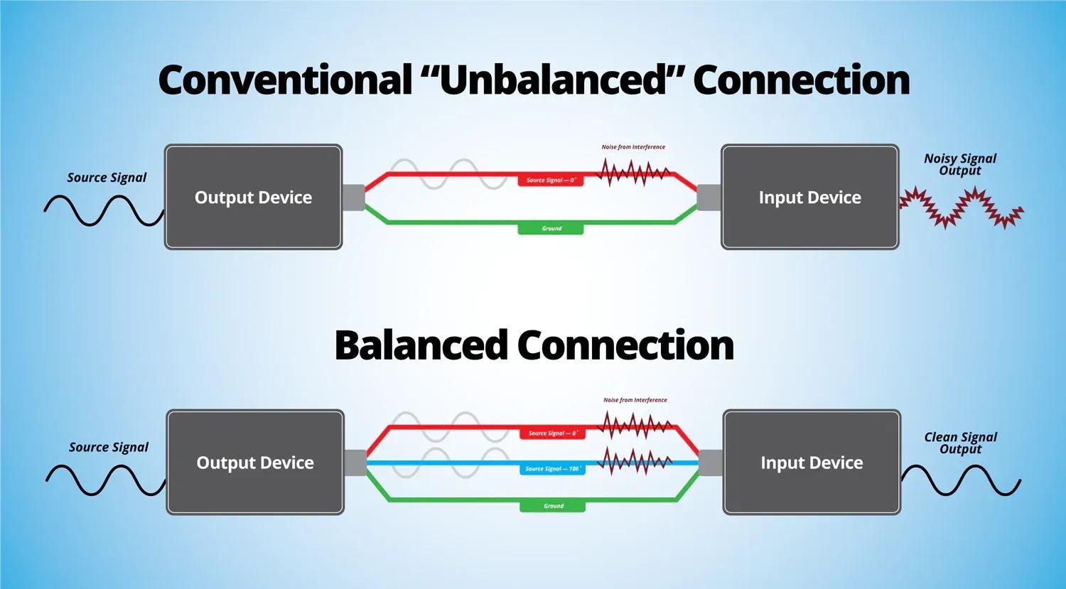
Most connections are unbalanced (RCA, 3.5mm TRS), which are more susceptible to noise but sufficient for short-distance use.
- Professional Audio
(Balanced Systems, +4 dBu Standard)
Typical devices:
- Mixing consoles
- DSP processors
- Professional amplifiers
- Audio matrices
- Conference systems
- Commercial audio systems
Standard reference level:
+4 dBu ≈ 1.23V RMS
This is the most widely used nominal operating level in professional audio.
Design priorities:
- Long-distance transmission
- Noise immunity
- High dynamic range
- System scalability
- Consistent gain structure
Connections are typically:
- XLR (balanced)
- TRS (balanced)
- Phoenix / Euroblock
Key point:
1.23V RMS is not “high”—it is standard in professional systems.
- Cinema Audio Systems
(Closer to Pro Audio Than Consumer)
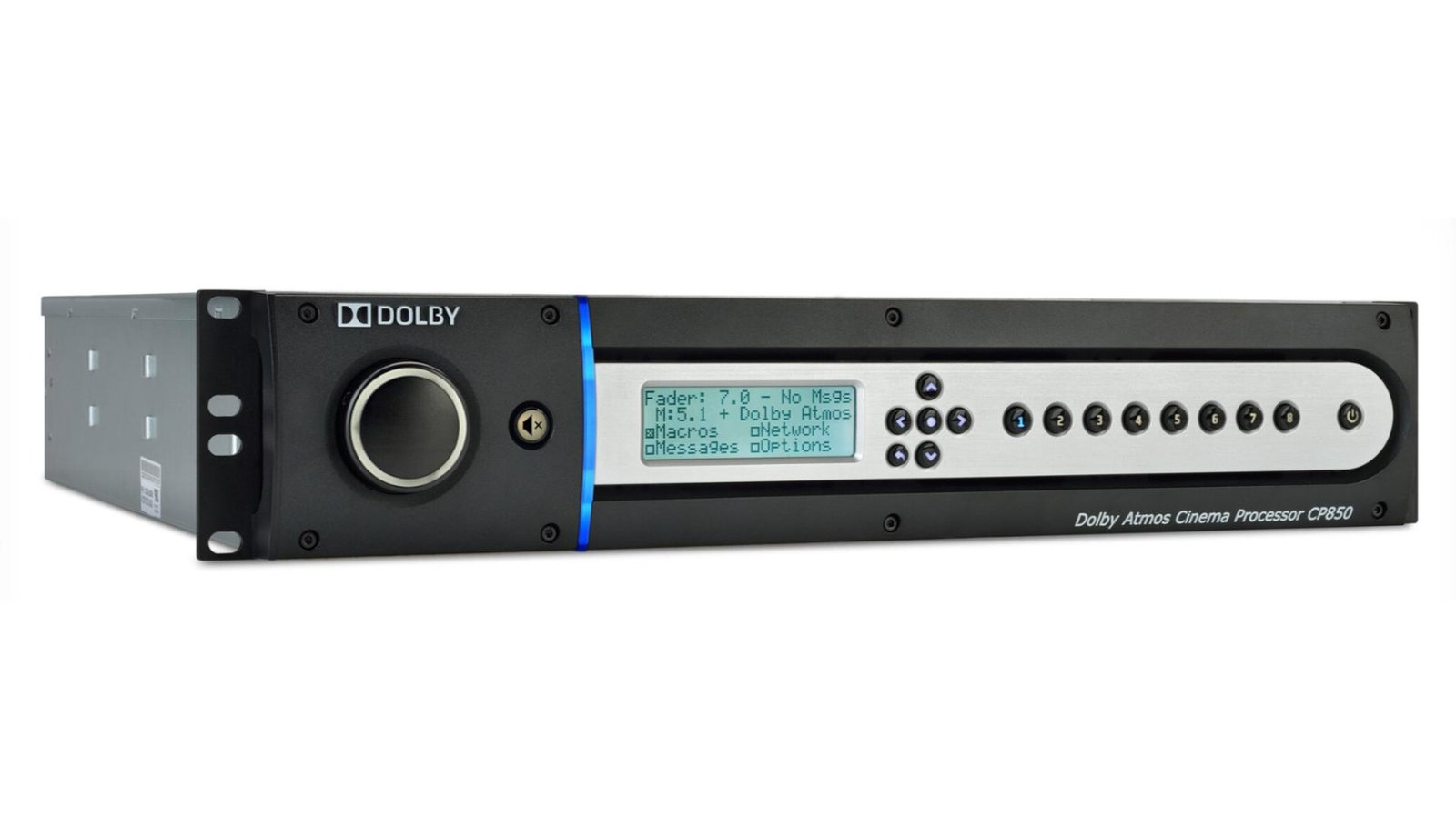
Typical signal chain:
- Cinema server
- Audio processor
- DAC
- DSP
- Multi-channel amplifiers
- Speaker arrays
Cinema systems prioritize:
- Precision gain structure
- Multi-channel consistency
- Headroom and dynamic range
- Stability and reliability
Typical output behavior:
Cinema DACs and processors often output around:
~1.23V RMS (professional line level)
If a receiving device expects only ~400 mV:
- This reflects input sensitivity, not a universal standard
- It does not imply the source output is incorrect
- Output Level vs System Matching
Analog audio must be evaluated as a system, not a single device.
Key parameters:
- Output voltage (source)
- Input sensitivity (receiver)
- Input impedance
- System gain structure
Example:
- Source output: 1.23V RMS
- Receiver full-scale input: 400 mV
Result:
- Receiver may overload easily
Solutions:
- Reduce input gain at receiver
- Lower output level at source
- Add passive attenuator
- Use DSP or preamp for gain staging
- Adjust analog output stage design
Key principle:
Mismatch is not a defect—it is a system integration issue.
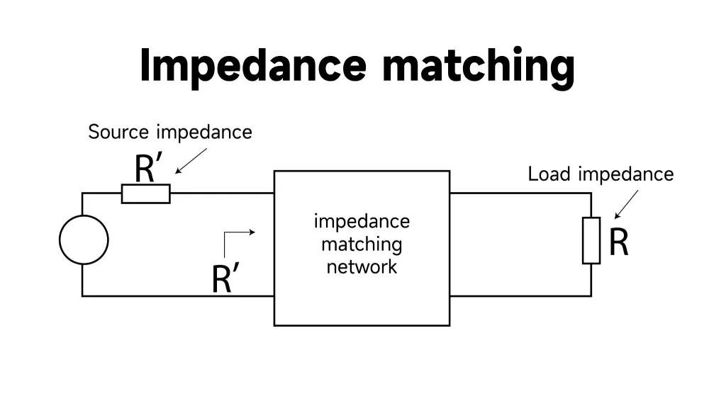
- Impedance: Not “Matching” but “Bridging”
A common misconception is:
Input impedance must equal output impedance.
This is incorrect for modern audio systems.
Modern audio uses:
Voltage bridging (not power matching)
Correct rule:
Input impedance ≥ 10× output impedance
Typical values:
- Output impedance: 50Ω – 600Ω
- Input impedance: 10kΩ – 50kΩ
Benefits:
- Minimal signal loss
- Stable frequency response
- Lower distortion
- Better compatibility
- Why Adding a Preamp “Fixes” the Problem
A common field issue:
“No sound directly, but works when adding a preamp.”
This is usually not a defect, but due to:
Possible causes:
- Insufficient signal level
Source output too low for receiver sensitivity - Impedance / load issues
Receiver input too low or poorly matched - Connection problems
- Balanced vs unbalanced mismatch
- Incorrect wiring
- Stereo vs mono issues
- Gain structure mismatch
No proper system gain planning
What a preamp does:
- Adds gain
- Provides buffering
- Improves drive capability
- Matches impedance
- Enables level control
- 400 mV vs 1.23V — How to Explain to Customers
If a customer requests lowering output from 1.23V RMS to 400 mV RMS, a proper explanation is:
1.23V RMS corresponds to a typical professional line level (~+4 dBu), widely used in professional and cinema audio systems.
A 400 mV requirement usually reflects the input sensitivity or gain structure of the receiving device, rather than a universal standard for all source outputs.
Therefore, adjusting the output level is possible for system compatibility, but it should be understood as a system-level optimization—not a correction of an incorrect design.
- Recommended Design Guidelines
| Application | Typical Output Level |
| Consumer electronics | 0.316V – 2V RMS |
| Professional audio | ~1.23V RMS (+4 dBu) |
| Cinema systems | Similar to pro audio |
| High-sensitivity inputs | Use attenuation or lower gain |
| Long cable runs | Use balanced outputs |
| Multi-device systems | Maintain consistent gain structure |
- Analog Input Architecture (AFE – Analog Front-End)
In practical audio system design, the analog input stage (AFE) plays a critical role in ensuring signal integrity before conversion into the digital domain.
9.1 Typical Analog Input Signal Chain
Signal flow:
Input Connector
→ Protection Circuit
→ Differential Receiver / Buffer
→ Gain Stage (Optional PGA)
→ Anti-aliasing Filter
→ ADC
→ DSP
9.2 Input Protection Stage
Purpose:
Protect downstream circuitry from damage and instability.
Typical implementation:
- ESD diodes
- TVS diodes
- Series resistors
- RC filtering
Design considerations:
- Avoid introducing distortion
- Handle hot-plug events
- Protect against voltage spikes
9.3 Differential Receiver / Buffer Stage
Purpose:
- Convert balanced signals to internal format
- Provide high input impedance
- Reject common-mode noise
Key characteristics:
- High CMRR
- Low noise
- Input impedance: 10kΩ – 50kΩ
9.4 Gain Stage (Programmable or Fixed)
Purpose:
Match signal level to ADC full-scale.
Options:
- Fixed gain
- Programmable Gain Amplifier (PGA)
- Digitally controlled analog gain
Importance:
- Prevent clipping
- Maximize SNR
- Support multiple input standards
9.5 Anti-Aliasing Filter (AAF)
Purpose:
Remove frequencies above Nyquist before ADC.
Design considerations:
- Cutoff below Nyquist
- Flat audio band response
- Minimal phase distortion
9.6 ADC Interface Stage
Purpose:
Convert analog signal to digital.
Key parameters:
- Full-scale input voltage
- Differential vs single-ended
- Dynamic range
👉 AFE must match ADC full-scale—not arbitrary voltage
9.7 Design Summary
| Stage | Function | Goal |
| Protection | Safety | Prevent damage |
| Buffer | Integrity | Low noise |
| Gain | Level match | Max SNR |
| AAF | Filtering | Prevent aliasing |
| ADC | Conversion | Accuracy |
9.8 Key Engineering Insight
The AFE defines:
- Noise floor
- Dynamic range
- Signal integrity
👉 DSP cannot fix a bad analog front-end
- DAC Output Stage Architecture
In professional systems, the DAC output stage defines final signal quality and level.
10.1 Typical DAC Output Signal Chain
Signal flow:
DAC → I/V Converter → LPF → Gain → Line Driver → Output
10.2 I/V Conversion Stage
Purpose:
Convert DAC current output to voltage.
Implementation:
- Precision op-amp
- Differential topology
10.3 Reconstruction Filter (Post-DAC LPF)
Purpose:
Remove high-frequency sampling artifacts.
10.4 Gain / Attenuation Stage
Purpose:
Set output level (1.23V / 2V / 400mV)
10.5 Line Driver Stage
Purpose:
- Drive cables
- Provide low impedance
- Support balanced output
Final Conclusion
There is no single “correct” analog output voltage across all audio systems. Consumer electronics, professional audio, and cinema environments each follow different design conventions.
In professional and cinema systems, ~1.23V RMS is a standard and appropriate output level. If a receiving device requires 400 mV, this typically reflects its input sensitivity or gain structure—not an error in the source.
The correct engineering approach is not to judge a single number, but to evaluate:
Signal level, impedance relationship, interface type, and overall system gain structure.